Although it’s not a question I hear frequently, it is a question I’m asked at times. What happens when a force is applied to two identical compression springs? The answer is just as easy as it may seem-the combination can handle twice as much force. If two springs have a rate of 500#/ inch of travel, the combination now produces a system capable of 1000#/in. You can look at it two ways-the system will produce 1000# in the one inch travel, or the system will only need to travel half the distance to produce 500#. Either way, there is a doubling of potential.
The same is true if more force is needed. If the force would need to quadruple, four springs will do the job. But what would be an application for multiple parts? If a device has a very short stroke, such as a weight scale, the device may need to create tremendous force with very little movement. A very high rate spring may not be possible because the wire size needed would be very large, well beyond the physical capacity of the device. Let’s say an application needed to produce 5000# in 0.100″ travel. This would require a spring rate of 50,000#/in. The required spring would be gigantic. But, it may be possible to use 20 much smaller springs that create 2500#/in, standing side by side in a cluster. This would deliver the force in the short deflection. Also, the cost of the 20 springs may actually be less than the one large spring because the smaller parts can be produced on standard spring making equipment with standard tooling- no special requirements for production.
Another very common use of this method is the nested spring. This is a spring assembly with two or three springs housed inside one another. Instead of both springs having the same spring rate, they have rates in percentile amounts to create the total rate required. For example, a spring system needs a total rate of 250#/in and cannot be achieved with just one spring.
The standard approach with a two-spring nest is to design the largest spring to handle 65% of the rate, which would be 162.5#/in. Then, a spring with an O.D. that will fit inside the I.D. of the larger spring can be designed to produce a rate of 87.5#/in. The total rate is accomplished. This application is quite common in engine valve springs. The main reason for this is that valve springs must be designed with very low stresses for very long life. One spring cannot accomplish the force in the space allowed for the spring to operate. But a two or three-spring nest can do the job very well and do it with stresses low enough to produce, theoretically, infinite life. The lesson to understand is that any compression spring placed beside another, that will operate in tandem, will combine forces. If three compression springs with the same free length are placed beside each other with rates of 100, 200 and 300#/in, the total rate of the system will be 600#/in. If all the springs have been designed for low stresses, the cost of the high life system with multiple parts will be negligible compared to the payback in performance.
Spring Fundamentals …
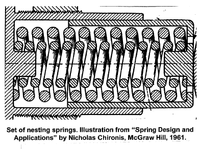
One caveat with nested springs- each spring must be the opposite winding direction of the spring next to it. The illustration below shows that the large spring is a right-hand coil direction, while the smaller, inner spring is left-hand wound. If nested springs are the same pitch direction, they can tangle and this would cause catastrophic failure of the mechanism. In most uses of compression springs, coil direction is only an issue in certain applications. But when springs operate one-inside-the-other, where one spring can possibly touch its mating spring, the opposite coil approach must be used.
By: Randy DeFord, Engineering Manager Mid-West Spring & Stamping