One of the desired functions of a compression spring is that it stays linear during its deflection. In layman’s terms, this means that the spring should produce the same load for every inch it moves. If a spring has a rate of 10 #/in, it will deliver 10 lbs for every inch of movement. A 2.0” movement will produce 20 lbs and a 3.0” movement will produce 30 lbs. And on and on until solid height is reached and no additional movement is possible.
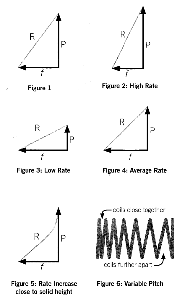
Let’s look at this in a simple graph form. A standard rate graph has two components – load (P) and deflection (f). This mean when one moves, so does the other. If we apply a load to a spring, it will move, and vice versa. (Fig. 1) If we join the two lines together, the resulting line represents the spring rate (R).
A spring with a high rate produces a lot of load with a small deflection, so the graph looks like this. (Fig. 2)
A spring with a low rate produces a small load with a large deflection. (Fig. 3)
A spring with an average rate would be somewhere between these two extremes and would look like this. (Fig. 4)
In the real world, the rate line is not straight for the entire travel to solid height. This is because the spring rate is produced by the active material in the spring. As the spring moves, the active material is functionally constant. That means no material is gained or lost. But as the spring gets closer to solid height, the end coils start to deaden and more and more material changes to dead coils, until all coils are dead at solid height. Due to this phenomenon, the average rate chart will actually look like this, which shows the increase in rate due to active coil loss. (Fig. 5) The majority of coil loss usually happens in the last 10 percent of deflection.
Some customers actually want the rate to increase as the spring moves. The many reasons for this are beyond the scope of this article. However, one of the applications is for race car suspension where an increase in rate is needed to improve traction (bite).
Increasing the rate of spring is a matter of deadening active material. To do this, the springmaker will put variable pitch into the coils. This is the process of varying the space between the coils in a manner that allows some coils to close sooner than others. Since the coils of a compression spring with a constant diameter all move the same distance, it’s a matter of making some coils closer together than others to create a rate increase. (Fig. 6) As the spring moves, the coils with the least pitch will close and create dead coils. The remaining coils now have a higher spring rate because of the fewer, remaining active coils. (Fig. 7). This scheme tends to produce a spring with two rates – one with all the coils open, and one with the closed coils and a remaining spring with a higher rate. Thus, a dual rate spring. (Fig. 8)
Another option is to have a spring with gradually increasing rate. This is done by making the pitch change subtle, increasing the space between the coils slowly and gradually so the coils close slowly, not abruptly as a dual rate spring. (Fig. 9). Since the rate is ever-increasing, it does not draw a straight-line rate as the other examples. It draws a curve as the rate. (Fig. 10). This is called a non-linear rate, also called a curve-linear rate.
These innovations in spring design are a new feature of the latest version of Advanced Spring Design (ASD), Release 7, which is now available from SMI.
So, a simple manipulation can serve a greater good by producing springs that alter their characteristics as they move. This application finds many functions and shows the versatility a spring can offer from a bit of simple spring trickery.
By: Randy DeFord, Engineering Manager Mid-West Spring & Stamping